Implementing XR Traffic Controller (XTC) in IP/MPLS & Segment Routing Service-Provider Networks.

Hello! Thank you for taking the time to view my blog and (possibly) follow along! I have been spending time preparing for the DEVNET SPAUTO specialist certification and I hope to create some great content thats publically available for those trying to achieve this cert.


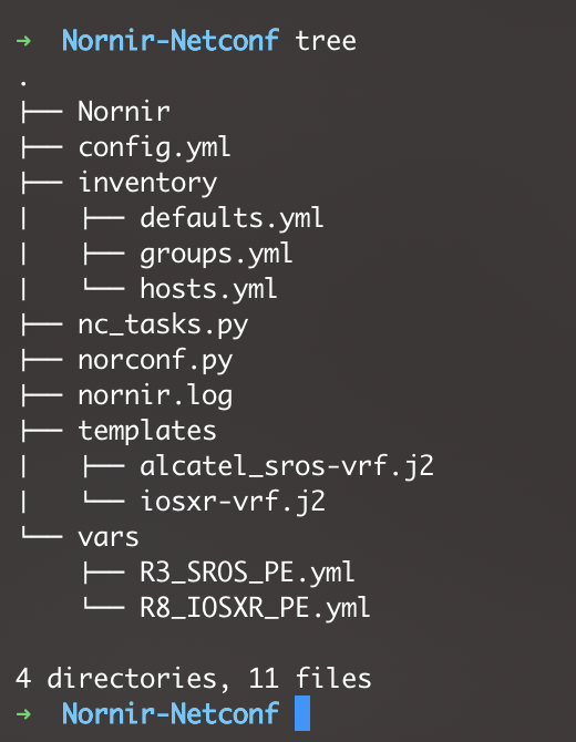
I’ve been gathering all the lab materials and automation I’ve created at the following personal repository:

SPAUTO DEVNET REPO

This material will also be included inside the WIKI pages for the repo.

For my DEVNET SPAUTO studies I’ve decided to dedicate quite some time to XTC as I have never used or seen this application in a production Service Provider environment. This topic is part of the Automation and Orchestration (30%) from the SPAUTO blueprint. 

4.6 Implement XR traffic controller
(including topology information transfer to XTC) 

Let’s gets some general terms out of the way before we continue with our Lab demo.

PCEP

PCEP is a hierarchical protocol, running over TCP port 4189. PCEP has two main functions:

  1. Path Computation Element (PCE) – A software controller acting as the server within the PCEP protocol. The PCE has a global view of the entire topology of a network and is able to centralize Path Computation and apply Traffic-Engineering policies. PCE can be clustered for redundancy.
  2. Path Computation Client (PCC) – The clients are network devices that can act as IP/MPLS Head-END Label Edge Routers (LER). The PCC devices receive operation instructions when signaling LSPs across a network (or multi-domain network) from the PCE. Optionally, local parameters can be used within the construct of the LSP when signaling alongside the information received from the PCE.

There are several implementations of PCE solutions, like Juniper’s SDN North Star and Cisco Open SDN controllers (OpenDayLight). However, in our lab topology we will be using a Cisco IOSXRv as the XTC (PCE) server. All other devices that inquiry information from the XTC device (PCE) will be the acting PCC clients. We have two devices that are acting as Route-Reflectors in our lab, we will also enlist them as a synchronized pair of XR Traffic Controllers.

BGP Link-State

BGP-LS is a newer extended address-family for BGP.  (AFI=16388, SAFI=71) – This family distributes network link-state information to the northbound controller (XTC/PCE or JunOS Northstar, OpendayLight, etc) This AFI provides BGP with Traffic-Engineering capabilities by mapping the network out, regardless of reachability or separated ASN/Domains. This is because the networks IGP (OSPF or ISIS) link-state database is exported (distributed) through BGP.

Okay, lets head over to the demo! Our goal in our demonstration will outline an LSP being deployed across our IP/MPLS Network with Segment-Routing as the underlying Transport. Also, an LSP will be deployed across a multi-domain (ISIS-CORE & ISIS-100) network. This specific multi-domain LSP is an incredible feature! Our PE1 LSP will have a far-end destination of PE100 which resides in a different domain and PE <> PE100 do not have network reachability to each other. 

XTC
XR Traffic Controller will be an IOSXRv device in our network. This device will have full PCE Server capabilities.

PRE-REQs:

There will be some basic information pertaining to Segment – Routing, but we will not go into great detail on how to configure SR in our network.

  1. Ensure your BGP sessions to the predetermined IOSXR device that will become the XTC Controller have BGP-LS enabled.
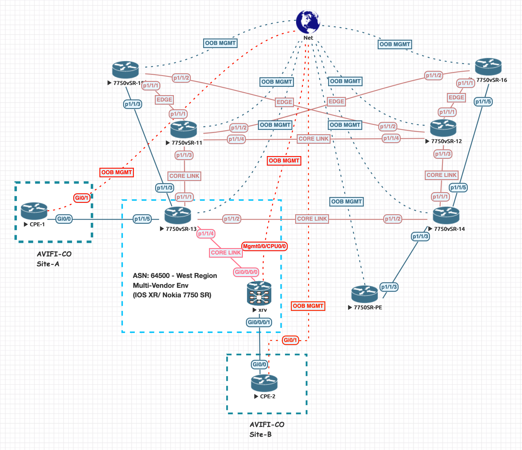
  2. Ensure link-state information is being distributed from your IGP. In our case, we are using IS-IS. From the topology map, we are redistributing link-state information from our Provider Edge devices PE4 and PE2 as they are the edge devices between this Multi-Domain (ISIS) topology. This information is all propagated back to the Route-Reflector which is going to be our XTC/PCE controller.
  3. Example IS-IS link-state distribution:
config t
router isis core
distribute link-state level 2
  1. Enable the link-state address family inside the BGP instance. Since I am enabling this on a Route-Reflector with a CLIENTS group, I will also add the family to the neighbor group. It’s important to add the address-family to the main BGP configuration otherwise the commit will fail. This family will also be added to the remote clients peering with this group.
config t
router bgp 65000
address-family link-state link-state
exit
neighbor-group CLIENTS
address-family link-state link-state
commit
  1. Enable XTC On the virtualized IOSXR Route Reflectors with state-sync to neighboring RR. I chose to use a RR for the sake of resources and ease to start as all BGP-LS information is readily available within this device.
pce
address ipv4 {{loopback0}}
logging no-path
!
state-sync ipv4 172.16.0.201
segment-routing
! 
end

Verify there is BGP LS information available at the RRs posing as the XTC PCE Server. This is a must before moving forward!

show bgp link-state link-state

Verify that link-state topology is available for the PCE. This command is being performed from the PCE/XR Traffic Controller (IOSXR RR)

show pce ipv4 topology

All of the hosts within our topology should be available in the link-state data. Visualizing the topology is easy, by piping the command in the following way:

RP/0/0/CPU0:AS65000_RR2#show pce ipv4 topology | include Host

Sat May 22 21:03:24.507 UTC

  Host name: AS65000_P1

      Host name: AS65000_PE1

      Host name: AS65000_PE3

  Host name: AS65000_P2

      Host name: 1720.1610.0022

      Host name: AS65000_P1

      Host name: AS65000_RR1

  Host name: AS65000_PE1

      Host name: 1720.1610.0022

      Host name: AS65000_P1

  Host name: AS65000_PE3

      Host name: AS65000_P1

      Host name: AS65000_PE4

  Host name: 1720.1610.0022

      Host name: AS65000_PE1

      Host name: AS65000_P2

      Host name: AS65000_PE100

  Host name: AS65000_PE4

      Host name: AS65000_P2

      Host name: AS65000_PE3

  Host name: AS65000_RR1

  Host name: AS65000_RR2

  Host name: AS65000_PE100

      Host name: 1720.1610.0022

      Host name: AS65000_PE101

  Host name: AS65000_PE101

      Host name: AS65000_PE100

LSP Configuration (Inter-Domain LSP)

Lets create an example LSP from our node AS65000_PE1 to our FOREIGN ISIS DOMAIN 100, PE101.
We will provide the traffic-eng configuration within MPLS to use our PCE peer (RR2). We will source our connection from our Loopback0 address at PE1.

Before we begin, lets check the computed path is available at the PCE XTC. If the path is not available, there could be some BGP-LS data missing or further troubleshooting is necessary before continuing. If there is no path, the LSP will not form at the PE.

Our PE device does NOT have reachability into ISIS Domain 100. We can verify this by attempting to reach the Loopback0 at PE101:

RP/0/0/CPU0:AS65000_PE1#show ip int br
Sun May 23 16:32:25.952 UTC

Interface                      IP-Address      Status          Protocol Vrf-Name
Loopback0                      172.16.0.11     Up              Up       default 

<------omitted------>

RP/0/0/CPU0:AS65000_PE1#ping 172.16.100.101

Sun May 23 16:08:08.862 UTC

Type escape sequence to abort.

Sending 5, 100-byte ICMP Echos to 172.16.100.101, timeout is 2 seconds:

UUUUU

Success rate is 0 percent (0/5)

RP/0/0/CPU0:AS65000_PE1#

However, if we perform a path computation from the XTC device, which has a full view of the network topology, we should be able to see some results:

RP/0/0/CPU0:AS65000_RR2#sh pce ipv4 path source 172.16.0.11 destination 172.16.100.101
Sun May 23 16:32:47.661 UTC

Path:
----:
Hop0: 10.0.0.2
Hop1: 10.0.0.6
Hop2: 10.0.0.10
Hop3: 11.0.0.5

Okay, so our XTC/PCE Server has a path to build an LSP! Start by configuring MPLS Traffic Engineering to use the PCE server.

conf t
!
mpls traffic-eng
 pce
  peer source ipv4 172.16.0.11
  peer ipv4 172.16.0.202
  !
  segment-routing
  stateful-client
!
commit
end

Now, let’s configure the new tunnel interface to use IGP metrics across our topology with a path-option determined by the PCE/XTC.

conf t
!
interface tunnel-te101
 ipv4 unnumbered Loopback0
 autoroute destination 172.16.100.101
 destination 172.16.100.101
 path-selection
  metric igp
 !
 path-option 1 dynamic pce address ipv4 172.16.0.202
!
end

The tunnel should now be built and established! Lets take a look at our tunnel details. Notice we are using the computed path from PCE! This path does not exists in our local route-table, particularly the last hop into unknown territory of ISIS Domain 100.

Name: tunnel-te101  Destination: 172.16.100.101  Ifhandle:0x1f0 
  Signalled-Name: AS65000_PE1_t101
  Status:
    Admin:    up Oper:   up   Path:  valid   Signalling: connected

    path option 1,  type dynamic pce 172.16.0.202 (Basis for Setup, path weight 220)
    G-PID: 0x0800 (derived from egress interface properties)
    Bandwidth Requested: 0 kbps  CT0
    Creation Time: Sun May 23 08:49:04 2021 (07:54:00 ago)
  Config Parameters:
    Bandwidth:        0 kbps (CT0) Priority:  7  7 Affinity: 0x0/0xffff
    Metric Type: IGP (interface)
    Path Selection:
      Tiebreaker: Min-fill (default)
    Hop-limit: disabled
    Cost-limit: disabled
    Path-invalidation timeout: 10000 msec (default), Action: Tear (default)
    AutoRoute: disabled  LockDown: disabled   Policy class: not set
    Forward class: 0 (default)
    Forwarding-Adjacency: disabled
    Autoroute Destinations: 1
    Loadshare:          0 equal loadshares
    Auto-bw: disabled
    Fast Reroute: Disabled, Protection Desired: None
    Path Protection: Not Enabled
    BFD Fast Detection: Disabled
    Reoptimization after affinity failure: Enabled
    Soft Preemption: Disabled
  History:
    Tunnel has been up for: 07:45:13 (since Sun May 23 08:57:51 UTC 2021)
    Current LSP:
      Uptime: 07:45:13 (since Sun May 23 08:57:51 UTC 2021)

  Path info (PCE computed path):
  Hop0: 10.0.0.3
  Hop1: 10.0.0.7
  Hop2: 10.0.0.11
  Hop3: 11.0.0.4
Displayed 1 (of 5) heads, 0 (of 0) midpoints, 0 (of 2) tails
Displayed 1 up, 0 down, 0 recovering, 0 recovered heads

The same tunnel creation has been applied from PE101 back towards PE1 from PE101.
Lets take a quick look at the tunnel configuration from PE101:

RP/0/0/CPU0:AS65000_PE101#show run interface tunnel-te11
Sun May 23 20:36:42.456 UTC
interface tunnel-te11
 ipv4 unnumbered Loopback0
 autoroute destination 172.16.0.11
 destination 172.16.0.11
 path-selection
  metric igp
 !
 path-option 1 dynamic pce address ipv4 172.16.0.202
!

And finally, let’s validate our MPLS te tunnel has a valid LSP path from PE101 to PE1

RP/0/0/CPU0:AS65000_PE101#traceroute mpls traffic-eng tunnel-te 11
Sun May 23 20:44:30.904 UTC

Tracing MPLS TE Label Switched Path on tunnel-te11, timeout is 2 seconds

Codes: '!' - success, 'Q' - request not sent, '.' - timeout,
  'L' - labeled output interface, 'B' - unlabeled output interface, 
  'D' - DS Map mismatch, 'F' - no FEC mapping, 'f' - FEC mismatch,
  'M' - malformed request, 'm' - unsupported tlvs, 'N' - no rx label, 
  'P' - no rx intf label prot, 'p' - premature termination of LSP, 
  'R' - transit router, 'I' - unknown upstream index,
  'X' - unknown return code, 'x' - return code 0

Type escape sequence to abort.

  0 11.0.0.4 MRU 1500 [Labels: 24033 Exp: 0]
L 1 11.0.0.5 MRU 1500 [Labels: 24020 Exp: 0] 0 ms
. 2 *
. 3 *
! 4 10.0.0.2 30 ms
RP/0/0/CPU0:AS65000_PE101#

MPLS LSP From XTC with Segment Routing as Transport

This scenario is almost identical, but we take full advantage of Segment-Routing as the transport. We have already configured our MPLS Traffic-Engineering to contact the PCE server for Path-Computation and everything has been verified. Now, while creating our Tunnel Interfaces, our Path-Options will be Dynamic from PCE but with Segment Routing. Lets take a look at what a tunnel will look like from PE1 to PE4 within the same IS-IS Domain:

RP/0/0/CPU0:AS65000_PE1#show run interface tunnel-te10044
Sun May 23 20:45:28.282 UTC
interface tunnel-te10044
 ipv4 unnumbered Loopback0
 destination 172.16.0.44
 path-selection
  metric igp
 !
 path-option 1 dynamic pce address ipv4 172.16.0.202 segment-routing
!

Great, our tunnel is configured and operationally up. Now, let’s review the Tunnel details and review the Path Option using Segment-Routing and the PCE Computed path by the XTC.

RP/0/0/CPU0:AS65000_PE1#show mpls traffic-eng tunnels 10044
Sun May 23 20:46:25.638 UTC


Name: tunnel-te10044  Destination: 172.16.0.44  Ifhandle:0x1d0 
  Signalled-Name: AS65000_PE1_t10044
  Status:
    Admin:    up Oper:   up   Path:  valid   Signalling: connected

    path option 1, (Segment-Routing) type dynamic pce 172.16.0.202 (Basis for Setup)
        Reroute pending (Path-option inuse by the current LSP has been modified)
      Bandwidth:        0 kbps (CT0) Priority:  7  7 Affinity: 0x0/0xffff
      Metric Type: IGP (interface)
      Path Selection:
        Tiebreaker: Min-fill (default)
        Protection: any (default)
      Hop-limit: disabled
      Cost-limit: disabled
      Path-invalidation timeout: 10000 msec (default), Action: Tear (default)
    Last PCALC Error [Reopt]: Sun May 23 08:42:33 2021
      Info: failed to find path
    G-PID: 0x0800 (derived from egress interface properties)
    Bandwidth Requested: 0 kbps  CT0
    Creation Time: Sun May 23 08:38:54 2021 (12:07:31 ago)
  Config Parameters:
    Bandwidth:        0 kbps (CT0) Priority:  7  7 Affinity: 0x0/0xffff
    Metric Type: IGP (interface)
    Path Selection:
      Tiebreaker: Min-fill (default)
      Protection: any (default)
    Hop-limit: disabled
    Cost-limit: disabled
    Path-invalidation timeout: 10000 msec (default), Action: Tear (default)
    AutoRoute: disabled  LockDown: disabled   Policy class: not set
    Forward class: 0 (default)
    Forwarding-Adjacency: disabled
    Autoroute Destinations: 0
    Loadshare:          0 equal loadshares
    Auto-bw: disabled
    Path Protection: Not Enabled
    BFD Fast Detection: Disabled
    Reoptimization after affinity failure: Enabled
    SRLG discovery: Disabled
  History:
    Tunnel has been up for: 12:05:04 (since Sun May 23 08:41:21 UTC 2021)
    Current LSP:
      Uptime: 12:05:04 (since Sun May 23 08:41:21 UTC 2021)
    Reopt. LSP:
      Last Failure:
        LSP not signalled, has no S2Ls
        Date/Time: Sun May 23 20:46:21 UTC 2021 [00:00:04 ago]

  Path info (PCE computed path):
  Hop0: 10.0.0.3
  Hop1: 10.0.0.7
  Hop2: 10.0.0.11
Displayed 1 (of 5) heads, 0 (of 0) midpoints, 0 (of 3) tails
Displayed 1 up, 0 down, 0 recovering, 0 recovered heads
RP/0/0/CPU0:AS65000_PE1#

Looks like everything is working! We could now deploy VPN services across this multi-domain network, as we have fully established a bi-directional LSP path from IS-IS Domain CORE and IS-IS Domain 100.

Troubleshooting commands

  • show mpls traffic-eng pce peer
    • Validate the session establishment with the XR Traffic Controller.
  • show mpls traffic-eng tunnels {tunnel_name}
    • View MPLS tunnel information in detail, such as PCE computated path.
  • traceroute mpls traffic-eng tunnel-te {tunel id}
    • MPLS traceroute

Summary

The power of the XR Controller to allow you dynamically create IP/MPLS or Segment-Routing Traffic Engineered tunnels is incredible. We have only scratched the surface, but this is enough to understand the concept of what XTC is providing for a large SP Network. There are some use-cases that have been shared by networks who are using this feature in production and it looks very promising. I can think of a specific merger in my career that we could have benefited greatly from this. As XTC has been fully implemented to be a feature of the IOSXR Family, it’s going to become incredibly easy to adopt in production networks. One thing to note is that BGP-LS is playing a KEY role in the success of XTC. Hopefully this has covered enough grounds for the SPAUTO exam and look forward to taking the exam and being prepared in this topic!

What’s Next?!

For my next blog, I will be using a similar use-case with XTC, but also automagically deploy a L3VPN or L2VPN with the help of an NSO instance! This will showcase how incredibly useful NSO can be when paired with XTC from the perspective of a Large Network Operator. Stay Tuned!

Nornir 3.0 – ::NETCONF:: Config Backup – XML/Jz0n

First things first: Review the code:

Code: https://github.com/h4ndzdatm0ld/nornir3-netconf-backup

The goal of this walkthrough is to backup configuration files from NETCONF enabled devices. Thanks to the flexibility of python, we have the choice to either back up the files as JSON or XML.. We will use the nornir_utils, write_file’ plugin which is now decoupled from Nornir (for those of you used to Nornir 2.x).

Ensure you have this plugin available, by installing it via pip:

pip3 install nornir_utils

Lets inspect our host file and rely on a custom data k, v: ‘operation: netconf-enabled’ to use as our Filter.

R3_SROS_PE:
  hostname: 192.168.0.222
  groups:
    - NOKIA
  data:
    region: west-region
    operation: netconf-enabled

R8_IOSXR_PE:
  hostname: 192.168.0.182
  groups:
    - IOSXR
  data:
    region: west-region
    operation: netconf-enabled

Lets begin our Nornir 3.0 runbook: Pay close attention to our filter, as we pass in (operation=”netconf-enabled”) from above.

Also ensure the additional libraries being imported, such as xmltodict and json, etc.. are present and installed.

from nornir import InitNornir
from nornir_utils.plugins.functions import print_result
import datetime, os, xmltodict, json, sys
from nornir_utils.plugins.tasks.files import write_file
from nornir_netconf.plugins.tasks import netconf_get_config

__author__ = "Hugo Tinoco"
__email__ = "hugotinoco@icloud.com"

# Specify a custom config yaml file.
nr = InitNornir("config.yml")

# Filter the hosts by the 'west-region' site key.
netconf_devices = nr.filter(operation="netconf-enabled")

A couple custom functions that we will take advantage of to assist us in creating directories and converting XML to JSON.

def create_folder(directory):
    """Helper function to automatically generate directories"""
    try:
        if not os.path.exists(directory):
            os.makedirs(directory)
    except OSError:
        print("Error: Creating directory. " + directory)


def xml2json(xmlconfig):
    """Simple function to conver the extract xml config and convert it to JSON str"""
    try:
        xml = xmltodict.parse(str(xmlconfig))
        return json.dumps(xml, indent=2)
    except Exception as e:
        print(f"Issue converting XML to JSON, {e}")

The create_folder function is a simple way to pass in a directory name and use the os library to create a new directory, if it’s not present. This is helpful as we will use this function to generate the ‘backup’ folder in our code to store our configuration files.

xml2json function is exactly that. We take in a XML string and return it in JSON.

The Bulk of the code:

def get_config(task, json_backup=False, xml_backup=False):
    """Use the get_config operation to retrieve the full xml config file from our device.
    If 'json_backup' set to True, the xml will be converted to JSON and backedup as well.
    """
    response = task.run(task=netconf_get_config)
    xmlconfig = response.result

    # Path to save output: This path will be auto-created for your below>
    path = f"Backups/{task.host.platform}"

    if json_backup == False and xml_backup == False:
        sys.exit("JSON and XML are both set to False. Nothing to backup.")

    # Generate Directories:
    create_folder(path)

    # Generate Time.
    x = datetime.datetime.now()
    today = x.date()

    # If the 'True' Bool val is passed into the xml_config task function,
    # convert xml to json as well and backup.
    if json_backup == True:
        json_config = xml2json(xmlconfig)

        write_file(
            task, filename=f"{path}/{task.name}_{today}_JSON.txt", content=json_config
        )
    if xml_backup == True:
        write_file(
            task, filename=f"{path}/{task.name}_{today}_XML.txt", content=xmlconfig
        )


def main():

    netconf_devices.run(task=get_config, json_backup=True, xml_backup=True)


if __name__ == "__main__":
    main()

Lets review. The get_config will take in the nornir task and have two boolean parameters which default to False, which are: XML backup and JSON backup. This allows us to specify if we want to backup the config in simple XML format, JSON format.. or both if you desire.

We start by extracting the config, using the nornir_netconf: netconf_get_config task. This retrieves the configuration and we extract the .result attribute and wrap it into a variable.

Now, we create a path as to where the files will be backed-up. We use f strings to format the directory structure: We specify a folder ‘Backups” followed by the platform of the device in which the current task is being executed against.

# Path to save output: This path will be auto-generated.
path = f"Backups/{task.host.platform}"

# Generate Directories:
create_folder(path)

We take this custom generated path and pass it in to our create_folder function and allow python to help us set up the directories.

One other thing to prepare for our file naming convention is a date to append at the end of the filename. Lets create a variable out of the datetime library and pass it in later on as we name our files.

    # Generate Time.
    x = datetime.datetime.now()
    today = x.date()

Finally, lets handle the boolean values and allow our program to make a decision on how to save the configuration (XML, JSON or both).

One thing to note, earlier in the code I added a system exception to exit the program if neither json_backup or xml_backup are set to True. There is no reason to execute and generate folders without a backup file to create and to place in the directories.

   if json_backup == False and xml_backup == False:
        sys.exit("JSON and XML are both set to False. Nothing to backup.")

    # If the 'True' Bool val is passed into the xml_config task function,
    # convert xml to json as well and backup.
    if json_backup == True:
        json_config = xml2json(xmlconfig)

        write_file(
            task, filename=f"{path}/{task.name}_{today}_JSON.txt", content=json_config
        )
    if xml_backup == True:
        write_file(
            task, filename=f"{path}/{task.name}_{today}_XML.txt", content=xmlconfig
        )

In the above code we take advantage of our xml2json custom function if we want to convert the retrieved XML config from our device and use our write_file Nornir Plugin to create and write the file. Something that’s also utilized from Nornir, is the task.host.name. If we are strategic enough we can even use our task.name of the current task and use it to our advantage. You can see we create the filename using f-strings and pass in the task.host.name alongside the today variable which was constructed earlier from the datetime library.

Execution:

The final result, depending on which format you chose to backup the configs will vary. In this demonstration, i’ve enabled both choices. See the tree directory below that was auto created for me and the write_file plugin from Nornir was helpful enough to save the configuration files. The Backups directory was generated, followed by the platform (task.host.platform) and finally the name of the file

filename = {task.host.name}_{date}_{XML_OR_JSON}

There you have it! A simple way to take advantage of the Nornir 3.0 framework and create backups of all your NETCONF enabled devices in either XML or JSON format.

Nornir 3.0 – Multi-Vendor L3VPN/VPRN (IOSxR/Nokia) IaC – Configuration Deployment via NETCONF/NORNIR

What a title to this post, right?

With the recent release of Nornir 3.0  – I wanted to explore the capabilities of Nornir and I already know, I will prob never use Ansible for Network Automation ever again.. 😉 However, the reason for this post is to give a high level overview of Nornir 3.0 and provide a guide to convert 2.x Nornir/Netconf scripts over to 3.0.

Some of the topics explored in this post will include but not limited to the following:

  1. Infrastructure as Code : (Jinja2 Template Rendering and YAML defined network state)
  2. Nornir 3.0.
    1. Installation
    2. Plugins
    3. Directory Structure
  3. NETCONF/YANG
  4. Netmiko

How to Follow Along

I’d recommed to download the code from my github and review the repo. Once you are familiar with the code you should be ready to start reading along.

CODE:

https://github.com/h4ndzdatm0ld/Norconf

Review the topology below: You will become the operator of this network throughout this journey. The solution you are implementing will ease the workload of the deployment engineers and possibly save your company some money. Depending on the issue that XYZ company is trying to solve, it’s becoming clear that not every one requires a high dollar solution to automate their networks with vendor specific nms, orchestrators, etc. Screen Shot 2020-09-21 at 3.58.38 PM

For those of you new to Nornir, it’s an automation framework written in Python.  If you are familiar with Ansible, you can adapt quite easily to Nornir as long as you know how to get around with python. You will quickly realize how flexible it is. One of my favorite features of Nornir is multithreading, allowing concurrent connections which in return makes this framework incredibly fast. We will discuss the topic of workers/threads a little more later in this post.

Getting Started

Begin by installing nornir with a simple pip3 install nornir 

Lets discuss the directory structure. You can see here there is quite a bit going on..

NOTE: All of the following files/directories have to manually be created. These are not autocreated. Take a minute and re-create the folders/files under a chosen filepath. I started a git repo and this is where I created all my folders.

We’ve created a defaults, groups and hosts yml file under our ‘inventory‘ directory. We actually have a config.yml file which specifies the path location of these filesScreen Shot 2020-09-22 at 9.37.12 AM. This config file is later passed into the nornir class that’s instantiated inside our python runbook, norconf.py. As always, our ‘templates‘ folder contains our Jinja2 files with the appropriate template files to render the configuration of the L3VPN and VPRNs for our multivendor environment. These are named according to their corresponding host platform and function.

Template Naming Example:

              • {iosxr}-(platform) -{vrf}-(purpose)-.j2 (extension). The actual template is XML data following yang models.  The reason to use the platform in the naming scheme, is to be able to use the host platform during our program execution and match the name of the file with the help of f strings. This is just one way to do it and you can find other ways that make more sense to your deployment.

Additional files in here, such as nc_tasks.py are adopted from Nick Russos project which uses nornir 2.X. He’s configured some custom netconf tasks at a time in which netconf was originally being introduced into Nornir. The Log file is self explanatory.

At the time of this writing, the nornir_netconf plugin is not yet available for Nornir 3.0 as a direct pip dowload/install.  What I have done is a series of try/except and mostly failures to get this to work. I had to take a step back and understand a lot of what’s happening under the hood of nornir.  I’ve cloned the REPO @ https://github.com/nornir-automation/nornir_netconf@first and tried to install it via Poetry, but this was mostly a huge waste of time and nothing worked, particularly with the plugin configuration of Nornir. I removed the installation and went the pip route straight from git.

I was able to install the the code by using pip + git using the following:

pip3 install git+https://github.com/nornir-automation/nornir_netconf@first

However, during the process I got an exception “AttributeError: module ‘enum’ has no attribute ‘IntFlag'” From some searching around, it’s due to a discrepency with using enum34. I ran the following to ensure the package was present and removed it.

pip freeze | grep enum34

➜ nornir_netconf-first pip3 freeze | grep enum34
enum34==1.1.10

Looks like I do have it in installed …  A quick, ‘pip3 uninstall enum34’ and re-ran the original pip3 install from git+git_page and the installation was successfull. I wonder what I broke by removing enum34 😉

Installing collected packages: nornir-netconf
Successfully installed nornir-netconf-1.0.0

Python 3.8.2 (v3.8.2:7b3ab5921f, Feb 24 2020, 17:52:18)
[Clang 6.0 (clang-600.0.57)] on darwin
Type “help”, “copyright”, “credits” or “license” for more information.
>>> import nornir_netconf
>>> print(SO FAR SO GOOD!)

I was having an issue with nornir netconf plugin originally and had to investigate how to manually register a plugin. That is before I found out how to get around the hurdle and install via git+pip. Here is the code I used to manually register the plugin in my runbook directly, in case anyone ever wants to register a new plugin..although a lot has to happen for any of this to work.

from nornir.core.plugins.connections import ConnectionPluginRegister
from nornir_netconf.plugins.connections import Netconf
ConnectionPluginRegister.register(“netconf”, ConnectionPluginRegister)
So, at this point – the netconf plugin is working.  The only problem I see with the nornir_netconf plugin is the returned output. After all this work, I realized if you do a print_result, to extract all the output – you don’t exactly get what you need to verify the sucess of the rpc-operation, such as the rpc_reply. This is a little troublesome. However, I did find that the custom netconf function written by Nick Russo gave me exactly what I need. At this time, I will not be using the nornir_netconf methods and instead import the custom russo tasks. See below:


def netconf_edit_config(task, target, config, **kwargs):
"""
Nornir task to issue a NETCONF edit_config RPC with optional keyword
arguments. Both the target and config arguments must be specified.
"""
conn = task.host.get_connection("netconf", task.nornir.config)
result = conn.edit_config(target=target, config=config, **kwargs)
return Result(host=task.host, result=result)

Importing this function, I am actually able to receive this rpc_reply from a successfull RPC operation. This is critical to the operation of my script – as I write conditional statements depending on the returning output of the tasks.run result. 

<?xml version=”1.0″?>
<rpc-reply message-id=”urn:uuid:28f57844-94cb-4ecc-b927-ba1f5318eab7″ xmlns:nc=”urn:ietf:params:xml:ns:netconf:base:1.0″ xmlns=”urn:ietf:params:xml:ns:netconf:base:1.0″>
<ok/>
</rpc-reply>
During the time of this writing I did express my concern on the lack of response from this edit_config function on the soon to be introduced nornir_netconf plugin to Patrick Ogenstad who is leading the development of the netconf plugin. Sounds like he may be updating the code to actually return rpc reply in the output, more to come on that. As of now, I will continue with Russo’s custom function as I see this being a requirement for any netconf python script to properply acknowledge the result. Additionally, his nc_tasks.py file contains a netconf_commit function which is a necessity for applying configurations against candidate target stores.
I treat NETCONF as an API. I need a response and I need a response NOW! 😉
Okay, enough about getting NETCONF to work on this new Nornir version.
Lets go over the inventory directory and the defaults, groups and hosts file.

The Host File:

R3_CSR:
hostname: 192.168.0.223
groups:
  – CSR
R3_SROS_PE:
hostname: 192.168.0.222
groups:
  – NOKIA
data:
  region: west-region
R8_IOSXR_PE:
hostname: 192.168.0.182
groups:
  – IOSXR
data:
  region: west-region
A simple yaml file that looks very familiar.. this should be an easy transition for all the Ansible folks. You define a host, hostname and specify a group to avoid duplication of data.
This is an example of the groups file – The inheritance from the group file is passed straight to each host that’s part of the group. If there is data inside the defaults yaml file, this is also inherited to all hosts. Something to keep in mind.

The Group File

Screen Shot 2020-09-22 at 12.23.32 PM
NOTE:
  • The  data.target key is inherited and called upon during the execution of rpc-edit config to point the operation against the correct netconf data store)
  • These connection options can make or break the process

The Config File

  • A config.yaml file must specify the location of the hosts, groups and defaults fiiles.
Screen Shot 2020-09-22 at 2.10.34 PM

Threads

We have specified 100 num_workers, which really means we can have up to 100 concurrent multithreaded sessions to devices.  The way I think about Nornir running process is everything you’re doing is in a giant ‘for loop’. The tasks runs through all the devices in the inventory (unless you specify a filter) one by one.  Although there isn’t a for statement written anywhere visible, you’re looping through all the devices in your inventory. However, using threads you’re actually doing this is parallel.  You could technically specify the ‘plugin: serial’ and not take advantage of threads.

Plugins

Before we move forward and begin writing our runbook/code – one thing I want to emphasize is the difference in Nornir 2.x and 3.x.  You must individually install the plugins! Here is a link to the current Nornir Plugins available and documentation/how – to from Nornir.
This part is incredibly important, as the power of Nornir is basically to become a sort of orchestartor and controller of these tasks which include running code that take advantage of these plugins. In our code we will use load_yaml, template_file, netmiko and the nornir_utils.
pip3 install nornir_utils
pip3 install nornir_netmiko
pip3 install nornir_jinja2

Run Book (Python Script of Compiled ‘tasks’)

As we begin writing our runbook for our project, lets instantiate the InitNornir class and pass in the custom config.yml file:
from nornir import InitNornir
from nornir_netmiko.tasks import netmiko_send_command
from nornir_utils.plugins.functions import print_result
from nornir_utils.plugins.tasks.data import load_yaml
from nornir_jinja2.plugins.tasks import template_file
from nornir_netconf.plugins.tasks import netconf_edit_config
from nc_tasks import netconf_edit_config, netconf_commit
import xmltodict, json, pprint
__author__ = ‘Hugo Tinoco’
__email__ = ‘hugotinoco@icloud.com’
# Specify a custom config yaml file.
nr = InitNornir(‘config.yml‘)

Filters

Screen Shot 2020-09-21 at 3.58.38 PM

What are filters and how do we create them? A filter is a selection of hosts in which you want to execute a runbook against. For our main example in this post, we are an operator who is in charge of deploying a L3VPN/VPRN in a multi-vendor environemnt at the core. This will include Nokia SR 7750 and Cisco IOSxR. However, our hosts file contains ALL of our devices that are available in our network. The L3VPN we are deploying is only spanning across our ‘west-region’ pictured on the bottom left of the topology above. There are two CPE’s, one attached to the Nokia 7750 and one to the Cisco IOSxR. In order to deploy this service, we want to specify within Nornir that we only need to execute the tasks against these two specific routers. The rest of the network doesn’t need to know about this service.  Below is a snippet of the ‘hosts.yml’ file which has customized region key and west-region item. You can see this is duplicated to the R8_IOSXR_PE device.  That’s it! We’ve identified common ground between these devices, being in the ‘west-region’ of our network.

R3_SROS_PE:
hostname: 192.168.0.222
groups:
  – NOKIA
data:
  region: west-region
R8_IOSXR_PE:
hostname: 192.168.0.182
groups:
  – IOSXR
data:
  region: west-region

Now lets write some code to ensure nornir knows this is a filter.

# Filter the hosts by the ‘west-region’ site key.
west_region = nr.filter(region=’west-region‘)
Wow, that was a lot.  This will come in handy once we are ready to execute the entire runbook in our main() function. Remember, the west-region is specified in the hosts file. This could also be inherited from the group file, if the hosts belongs to said group.

Infrastructure as Code

We’ll be extracting information from our Yaml files which are variables inputted by the user along side our Jinja2 templates consisting of our Yang Models. We use Jinja2 to distribute the correct variables across our yang models for proper rendering. For distributing  the configurations via NETCONF across our core network we enlist the help of Nornir to manage all of theses tasks. We’re allowing Nornir to handle the flow and procedures to ensure proper deployment.

VARS

Below is the yaml file containing our vars which will be utilized to render the j2 template.  The following is for the Nokia platform:

VRF:
  – SERVICE_NAME: AVIFI
    SERVICE_ID: ‘100’
     CUSTOMER_ID: 200
    CUSTOMER_NAME: AVIFI-CO
    DESCRIPTION: AVIFI-CO
    ASN: ‘64500’
    RD: 100
    RT: 100
    INTERFACE_NAME: TEST-LOOPBACK
    INTERFACE_ADDRESS: 3.3.3.3
    INTERFACE_PREFIX: 32
If you are not familiar with how a L3VPN works, this is the time you can review this topic. In order to properly configure a L3VPN service for your customer, you must provide a service name for your VRF. In the Nokia/SROS world, you must also provide a customer_id, which is passed into the creation of the service for the specific customer. A customer name is also passed into the vars file as you want to specify the name of the customer not just a numerical value(id). The Autonomous system is a requirement for the VRF, along side the route-target and route-distinguisher.  Additionally, we will be creating a loopback interface within the VRF for testing purposes. The goal here is not only to deploy the service but to validate L3 Connectivity across the core via Multi-Protocol BGP (MP-BGP). MPLS has already been configured in the core.

Jinja 2 – yang:sr:conf

There are so many important pieces to construct this automation project. The J2 template file, must include everything that is necessary to create this service. Below is the example for the Nokia device. Please see my code via the github repo at the top of this document to review the IOSxR J2 Template file. There are also supporting documents at the end of this document if you need more information on Jinja2


{% for VRF in data %}
<config>
<configure xmlns="urn:nokia.com:sros:ns:yang:sr:conf">
<service>
<customer>
<customer-name>{{VRF.CUSTOMER_NAME}}</customer-name>
<customer-id>{{VRF.CUSTOMER_ID}}</customer-id>
</customer>
<vprn>
<service-name>{{VRF.SERVICE_NAME}}</service-name>
<service-id>{{VRF.SERVICE_ID}}</service-id>
<admin-state>enable</admin-state>
<customer>{{VRF.CUSTOMER_NAME}}</customer>
<autonomous-system>{{VRF.ASN}}</autonomous-system>
<route-distinguisher>{{VRF.ASN}}:{{VRF.RD}}</route-distinguisher>
<vrf-target>
<community>target:{{VRF.ASN}}:{{VRF.RT}}</community>
</vrf-target>
<auto-bind-tunnel>
<resolution>any</resolution>
</auto-bind-tunnel>
<interface>
<interface-name>{{VRF.INTERFACE_NAME}}</interface-name>
<loopback>true</loopback>
<ipv4>
<primary>
<address>{{VRF.INTERFACE_ADDRESS}}</address>
<prefix-length>{{VRF.INTERFACE_PREFIX}}</prefix-length>
</primary>
</ipv4>
</interface>
</vprn>
</service>
</configure>
</config>
{% endfor %}

Runbook Walkthrough


def get_vrfcli(task, servicename):
''' Retrieve VRF from IOSXR
'''
vrf = task.run(netmiko_send_command, command_string=f"sh vrf {servicename} detail")
print_result(vrf)
def get_vprncli(task, servicename):
''' Retrieve VPRN from Nokia
'''
vprn = task.run(netmiko_send_command, command_string=f"show service id {servicename} base")
print_result(vprn)
def cli_stats(task, **kwargs):
''' Revert to CLI scraping automation to retrieve simple show commands and verify status of Services / L3 connectivity.
'''
# Load Yaml file to extract specific vars
vars_yaml = f"vars/{task.host}.yml"
vars_data = task.run(task=load_yaml, file=vars_yaml)
# Capture the Service Name:
servicename = vars_data.result['VRF'][0]['SERVICE_NAME']
if task.host.platform == 'alcatel_sros':
get_vprncli(task, servicename)
elif task.host.platform == 'iosxr':
get_vrfcli(task, servicename)
else:
print(f"{task.host.platform} Not supported in this runbook")

Our overall goal is to deploy the VPRN/L3VPN. We start by creating a few custom functions.

We create get_vrfcli and get_vprncli. These two functions take advantage of netmiko_send_command plugin and are using platform specific cli commands. We will use these two commands to retrieve the service status. Then we take the two functions and wrap them inside cli_stats.  We load the yaml file using the load_yaml plugin from Nornir. Once the task is executed, we drill into our vars file and extract the service name as a variable from our loaded dictionary (yaml file). This variable is then passed into the get_vrpncli/get_vrfcli functions to execute against our devices. At this point, if we execute the cli_stats tasks against our west-region, we can use conditional statements to execute the correct command against the correct platform device. The way in which we access the platform, is by simply digging into the task.host.platform key. This will return the value of the key.

NOTE:

I am working on a video tutorial and demonstration of Nornir 3.0. During the video, I will create additional tasks in which verify the L3 Connectivity via simple ping commands.

Bulk of the Code:


def iac_render(task):
''' Load the YAML vars and render the Jinja2 Templates. Deploy L3VPN/VPRN via NETCONF.
'''
# Load Yaml Files by Hostname
vars_yaml = f"vars/{task.host}.yml"
vars_data = task.run(task=load_yaml, file=vars_yaml)
# With the YAML variables loaded, render the Jinja2 Template with the previous function: iac_render.
template= f"{task.host.platform}-vrf.j2"
vprn = task.run(task=template_file, path='templates/', template=template, data=vars_data.result['VRF'])
# Convert the generated template into a string.
payload = str(vprn.result)
# Extract the custom data.target attribute passed into the group of hosts to specifcy 'candidate' target
# configuration store to run the edit_config rpc against on our task.device.
# IOSXR/Nokia take advantage of candidate/lock via netconf.
deploy_config = task.run(task=netconf_edit_config, target=task.host['target'], config=payload)
# # Extract the new Service ID Created:
if task.host.platform == 'alcatel_sros':
for vrf in vars_data.result['VRF']:
serviceid = vrf['SERVICE_ID']
servicename = vrf['SERVICE_NAME']
# Ensure the customer – id is always interpreted as a string:
customer = vrf['CUSTOMER_ID']
customerid = str(customer)
if task.host.platform == 'iosxr':
for vrf in vars_data.result['VRF']:
servicename = vrf['SERVICE_NAME']
serviceid = None
rpcreply = deploy_config.result
# if 'ok' in result:
if rpcreply.ok:
print(f"NETCONF RPC = OK. Committing Changes:: {task.host.platform}")
task.run(task=netconf_commit)
# Validate service on the 7750.
if task.host.platform == 'alcatel_sros':
nc_getvprn(task, serviceid=serviceid, servicename=servicename, customerid=customerid)
elif task.host.platform =='iosxr':
pass
# Duplicate the getvprn function but for iosxr
elif rpcreply != rpcreply.ok:
print(rpcreply)
else:
print(f"NETCONF Error. {rpcreply}")

view raw

gistfile1.txt

hosted with ❤ by GitHub


Lets review the iac_render function. We simply load our yaml vars and render our j2 templates. Special attention to the following:

template= f”{task.host.platform}-vrf.j2″
This allows us to properly select a template that matches the host during the execution of the task. Using our f-strings, we pass in the task.host.platform and append the ‘-vrf’ which in turn matches the name of our stored xml templates inside our templates directory. Example: “iosxr-vrf.j2”

At this point we have our payload to deploy against our devices. One thing to note, the result of the rendered template using the nornir plugin, template_file is a Nornir Class. Make sure this gets converted to a str: “payload = str(vprn.result)”. We will pass this into our netconf_edit_config task as the payload to deploy via netconf.

deploy_config = task.run(task=netconf_edit_config, target=task.host[‘target’],             config=payload)

Lets examine this line of code. We assign ‘deploy_config’ as the variable for the returning output of our task. The task we will execute is the ‘netconf_edit_config‘ function. Again, this is a wrapper of ncclient, which I hope you’re familiar with – if not, please give it a google search or review the additional resources at the bottom of the doc.
Now, the’ target=task.host[‘target’]’ is the data store to use during our rpc NETCONF call. We specified this for our host inside our groups file. See below:

NOKIA:
username: ‘admin’
password: ‘admin’
platform: alcatel_sros
port: 22
data:
    target: candidate 

NETCONF has three data stores in which we can execute configuration changes against.

  1.  Running
  2.  Startup
  3.  Candidate

In my opinion, candidate is the most valuable operation. We are able to input a config change, validate and once we are sure of the changes we must commit the change. As the operator of this network, we must be sure not to cause any outages or create any rippling effects from our automation. We will insepct the RPC reply and ensure all is good and if so, we will commmit out changes for the customer.

Line 23, has a conditional statement where we dig into the actual platform of the hosts that’s running within our task. We simply compare it to alcatel_sros or iosxr, as those are our two core devices in this example. We extract a couple different items in the result of our loaded yaml file which we will use to return some output to the screen and provide results in a readable format. We do the same with our iosxr results.

At this point, the netconf_edit_config wrapper for ncclient should have executed the netconf rpc and editted the configuration.

We store the reply in a variable called rpcreply, by extracting the .result attribute out of our original deploy_config variable. This gives us the xml reply and we can check the result of the reply by using ‘if rpcreply.ok:’

Line 42 gives us a simple feedback to let us know the result has returned OK. We now run the netconf_commit  task and confirm the change.

Finally, lets validate some of the services applied and use our custom function ‘nc_getvprn’ against our Nokia 7750.

nc_getvprn(task, serviceid=serviceid, servicename=servicename,   customerid=customerid)

Earlier, we extrracted some vars from our yaml file and loaded them into script as the following: ‘serviceid’, ‘servicename’ and ‘customerid’. We use these variables to execute the task and get some information by parsing the result of the netconf_get_config rpc call. We process this information by using xmltodict.parse and converting the xml to a Python dictionary. We compare the values found inside our running configuration against the desired state of our network element. Infrastructue as code is fun right? Once we do some comparasion of our items, we return meaningful output to the screen to let us, the operator know that everything is configured as expected.

If you are not familiar with xmltodict, I will provide additional references at the bottom of this document.

At the time of this writing I only have completed the compliance check against the Nokia sros device. I will most likley be extending this code to do the same against the IOSxR device. Below is the customer ‘nc_getvprn” function which we just described.


Execution


def main():
west_region.run(task=iac_render)
west_region.run(task=cli_stats)
if __name__=="__main__":
main()

view raw

nornir-final

hosted with ❤ by GitHub

It’s that easy. We run our tasks against our filter, west_region to narrow down our hosts for our multi-vendor environment. Lets review the output!


➜ Norconf git:(master) ✗ python3 norconf.py
NETCONF RPC = OK. Committing Changes:: alcatel_sros
NETCONF RPC = OK. Committing Changes:: iosxr
SR Customer: AVIFI-CO
SR Customer ID: 200
SR Service Name: AVIFI
vvvv netmiko_send_command ** changed : False vvvvvvvvvvvvvvvvvvvvvvvvvvvvvvvvvvv INFO
===============================================================================
Service Basic Information
===============================================================================
Service Id : 100 Vpn Id : 0
Service Type : VPRN
MACSec enabled : no
Name : AVIFI
Description : (Not Specified)
Customer Id : 200 Creation Origin : manual
Last Status Change: 09/18/2020 08:56:02
Last Mgmt Change : 09/18/2020 08:56:02
Admin State : Up Oper State : Up
Router Oper State : Up
Route Dist. : 64500:100 VPRN Type : regular
Oper Route Dist : 64500:100
Oper RD Type : configured
AS Number : 64500 Router Id : 10.10.10.3
ECMP : Enabled ECMP Max Routes : 1
Max IPv4 Routes : No Limit
Auto Bind Tunnel
Resolution : any
Weighted ECMP : Disabled ECMP Max Routes : 1
Max IPv6 Routes : No Limit
Ignore NH Metric : Disabled
Hash Label : Disabled
Entropy Label : Disabled
Vrf Target : target:64500:100
Vrf Import : None
Vrf Export : None
MVPN Vrf Target : None
MVPN Vrf Import : None
MVPN Vrf Export : None
Car. Sup C-VPN : Disabled
Label mode : vrf
BGP VPN Backup : Disabled
BGP Export Inactv : Disabled
LOG all events : Disabled
SAP Count : 0 SDP Bind Count : 0
VSD Domain : <none>
——————————————————————————-
Service Access & Destination Points
——————————————————————————-
Identifier Type AdmMTU OprMTU Adm Opr
——————————————————————————-
No Matching Entries
===============================================================================
^^^^ END netmiko_send_command ^^^^^^^^^^^^^^^^^^^^^^^^^^^^^^^^^^^^^^^^^^^^^^^^^^
vvvv netmiko_send_command ** changed : False vvvvvvvvvvvvvvvvvvvvvvvvvvvvvvvvvvv INFO
Thu Sep 24 09:10:56.099 UTC
VRF AVIFI; RD 64500:100; VPN ID not set
VRF mode: Regular
Description AVIFI-CO
Interfaces:
Loopback100
Loopback200
Address family IPV4 Unicast
Import VPN route-target communities:
RT:64500:100
Export VPN route-target communities:
RT:64500:100
No import route policy
No export route policy
Address family IPV6 Unicast
No import VPN route-target communities
No export VPN route-target communities
No import route policy
No export route policy

view raw

nornir-result

hosted with ❤ by GitHub

From the output above, we deployed our L3VPN (IOSxR) and VPRN (NOKIA) device. After we take full advantage of our IaC+Nornir, we return back to our CLI Scraping automation and rely on Netmiko to run simple show commands to view the VRF is actually present and validate the services.

Additional Resources:

Kirk Byers Nornir 3.0 Docs

Jinja 2 – Render Templates

NETCONF – ncclient (Github)

XMLTODICT

LISP – Loc/ID Separation Protocol (FREE ENCORE LAB)

I have decided to continue my education and dig deeper into the Cisco world. As an engineer that’s basically dedicated the past 4 years of his life into a Nokia IP/Routing world, I somtimes need to take a step back and spend time to understand other vendor’s platform and emerging technologies. I recently passed the Cisco DevNet exam and well, it made me realize there is a lot of gaps in my knowledge regarding Cisco. I’m currently studying for ENCORE and hope to grasp some of the unfamiliar knowledge and refresh up on all the basics, OSPF, BGP, STP, etc..  I hold a  NRS II, which is basically a CCNP, but it involves a detailed 4 hour live router lab that must be performed in person under strict monitoring rules. My goal is to become a CCNP/NRS II by the end of the year. I’ve chosen to start labbing LISP, as SD-Access is an emplementation of VXLAN with LISP control plane. These are technologies I will be digging much deeper into as I have not had experience with them professionally.

Lets talk about Overlay Tunnels.  An overlay network is a logical or virtual network on top of a physical transport network, which is also known as the underlay network.

Some overlay tunneling technologies include, GRE, IPsec, LISP, VxLAN and MPLS. In this POST, I want to concentrate on LISP.

The main goal of LISP is to address the scalability problems with the growing route table of the internet.

A few KeyTerms to remmember:

  • Endpoint Identifier (EID) – The IP address of an endpoint within a LISP Site. EIDs are the same ip addresses in use today on endpoints (v4/v6).
  • LISP Site – The name of the Site where EID’s and LISP routers live.
  • Ingress Tunnel Router (ITR) – LISP Routers that LISP-encapsulate IP Packets coming from EIDs that are destined outside the LISP site.
  • Egress tunnel router (ETR) – ETRs are LISP routers that de-encapsulate LISP-encapsulated IP packets coming from sites outside the LISP site and destined to EIDs within the LISP site. 
  • Tunnel Router (xTR) – Routers that perform ITR and ETR Functions. (Most routers wihtin an LISP domain)
  • Proxy ITR (PITR) -PITRS are for non-LISP sites that send traffic to EID destinations
  • Proxy ETR (PETR) – PETRS act just like ETRS, but for EIDs that send traffic to destinations at non-LISP sites.
  • LISP Router – Any router that performs any LISP functions.
  • Routing Location (RLOC) – RLOC is an IPv4/v6 address of an ETR that is Internet facing or core network facing.
  • Map Server (MS) – This is a network device (Router) that learns EID to prefix mapping entries from an ETR and stores them in a local EID-to-RLOC mapping database.
  • Map Resolver (MR) – Network device that receives LISP-encapsulated map requests from an ITR and finds the appropriate ETR to answer those requests by consulting the map server.
  • Map Server/Map Resolver (MS/MR) – When MS and MR are implemented on the same device.Screen Shot 2020-07-23 at 4.30.40 PM

The advantage and key control plane feature of LISP is the efficiency and scalability of the on-deman routing, as it’s not a PUSH model such as BGP or OSPF. LISP utilizes a pull model where only the requested routing information is provided, instead of a full table.

This entire operation sure feels like a DNS query. I felt this way the second I was updating the MS/MS in my lab telling it what the EID’s prefixes within my LISP site was. It’s an easy way to think of LISP and maybe that will click easier in your head.

Lets review the registration process for Site: Avifi-A on the left, CSR-A12.

Screen Shot 2020-07-23 at 4.30.40 PM

If the traffic flow is from Site Avifi – B to Site Avifi-A, the Avifi-A router will be the ETR in this instance(technically, the device is confiured as itr/etr as it’s providing both functions.). Avifi-A will need to adervtise it’s Lo0 address to the MS/MR.

The EID for Avifi-A : 192.168.1.0/24 – This includes the Lo0 that’s currently reachable on the router.

The RLOC is the interface address configured on Gi1 on the Avifi-A router. Although not displayed on the image, it’s 10.0.1.2.

Here is an example configuration snippet of the database-mapping command to include the EID and the RLOC.

R2-Avifi-A#show run | sec lisp
router lisp
database-mapping 192.168.1.0/24 10.0.1.2 priority 1 weight 100
ipv4 itr map-resolver 10.0.1.1

The Lab has since expanded to add CPE’s with traditional OSPF routing between the xTR and the CPE. There is redistribution of connected subnets (loopbacks) and the xTR has an updated database to include this loopback.

I’ve also included an IPSEC via VTI that has an OSPF adjacency across a simulated ISP network with public IP addresses. This allows us to take advantage of a PxTR which is a PITR and PETR router collapsed into one device.  I’ve uploaded this EVE-NG LAB into my blog for you to downoad and play with..who knows, maybe ever learn about LISP!

I’ve left fun exercise for your to practice, if you wish to use this lab.

TASK:

Establish the underlay network for Site B’s CPE to the PE. Once that’s completed, ensure the EID is updated on the MS/MR and that the EID is reachable via LISP overlay network.

_Exports_eve-ng_export-20200724-023627


Programatically Enable NETCONF and MD-CLI on Nokia – SROS Using Netbox API. (Part 2)

CODE: https://github.com/h4ndzdatm0ld/sros-enable-netconf/blob/master/enable-netconf-netboxapi.py

Okay, so you’re still reading? Lets keep digging into the mind of the network team and see how this exercisce is going..  So far, we’ve got a command line tool that we can target one specific node and deploy a script to enable MD-CLI, Yang Models from Nokia and of course, NETCONF. But, how far does this really get us? Really, it’s usefull to test on a handful of nodes and see the behaviour and response to our scripts in a lab environemnt. I’ve tested it on several SROS 19.10R3 A8’s and SR1’s.

It’s time to elaborate on the script and use the tool the Avifi has already deployed and mainted, Netbox. If you haven’t heard of Netbox, google it. In short it’s an IPAM/DCIM and so much more. The customer has requested we do not make any changes to anything in the subnet 10.0.0.0/16, anything else is fair game.  Lucky for us, the IP’s we need have been tagged with ‘7750’, would you believe that?! We’ll use a filter on our API call to extract the IP’s that we need and loop through them doing, but also leaving out anything in the 10xspace. We’ve taken a step back from the command line driven tool model and make a few things a bit more static, by using default arguements from the argparse package.

Before writing any more code, lets pull an API token from the Netbox server.

Here are the instructions: https://netbox.readthedocs.io/en/stable/api/authentication/

We’ll put this token into our application.. not the most secure way of doing this, but for simplicity – we’ll store it in a var in plain text for now. In my opinion, the authorization handled by the netbox administrator should theoretically prevent us from doing anything catastrophic when providing a user with an API token. .. in a perfect world 😉

Lets get to coding! Screen Shot 2020-05-19 at 1.16.50 PM

I thought about passing the argsparsge args into this function and having the ability to pass in an arguement as a ‘tag’ to filter by on the API call, but I didn’t think that was necessary. Although it could be usefull later and a quick and easy modification.

The code above shows nb as the pynetbox authenticated api requests. We then use the application form ‘ipam.ip_addresses‘ and filter by a tag, in which we pass in as an arguement on the function.

The customer requested we skip over any device in the RFC 10 Space, so we create a conditional statement to evaluate the IP’s. Note this is a very broad catch, it should be redefined if this were production as 192, could very much contain ’10.’. I would recommend adding the startswith() function and be more specific. But for now, this works.


for x in SR7750:
ip = get_ip_only(x)
if '10' in ip:
print(f'skipping {ip} – We do not want to edit nodes in this subnet.')
elif '192' in ip:
sros_conn = net_connect = ConnectHandler(**router_dict(args,ip,SSH_PASS))
# Establish a list of pre and post check commands.
print('Connecting to device and executing script…')
send_single(sros_conn, 'show system information | match Name')
enabled = sros_conn.send_command('show system netconf | match State')
if 'Enabled' in enabled:
print(f"{ip} already has NETCONF enabled. Moving on..")
disconnect(sros_conn)
time.sleep(2)
print('\n')
try:
netcbackup(ip, NETCONF_USER, NETCONF_PASS)
except Exception as e:
print(f"{e}")
continue

view raw

condiitional ip

hosted with ❤ by GitHub


We loop through the IP results in which we got back from the API call and strip the subnet mask using regular expressions. We than pass the IP into our Netconf connection and proceed to get the configuration. Here is a snippet of the RegEX function to strip the /subnet mask from the IP.


def get_ip_only(ipadd):
''' This function will use REGEX to strip the subnet mask from an IP/MASK addy.
'''
try:
ip = re.sub(r'/.+', '', str(ipadd))
return ip
except Exception as e:
print(f"Issue striping subnetmask from {ipadd}, {e}")

view raw

get_ip

hosted with ❤ by GitHub

Finally, I created a function that will establish the initial netcon connection and get.config. We save the netconf element to a file and open it to be able to parse the xml contents, with xmltodict. With this, we extract the system host name and use it as a var to create a folder directory and a file name. We save the running configuration in xml format.


def netcbackup(ip, NETCONF_USER, NETCONF_PASS):
''' This function will establish a netconf connection and pull the running config. It will write a temp file,
read it and convert the XML to a python dictionary. Once parsed, we'll pull the system name of the device
and create a folder structure by hostname and backup the running config.
'''
try:
# Now let's connect to the device via NETCONF and pull the config to validate
nc = netconfconn(ip, NETCONF_USER, NETCONF_PASS)
# Grab the running configuration on our device, as an NCElement.
config = nc.get_config(source='running')
# XML elemnent as a str.
xmlconfig = to_xml(config.xpath('data')[0])
# Write the running configuration to a temp-file (from the data/configure xpath).
saveFile('temp-config.xml', xmlconfig)
# Lets open the XML file, read it, and convert to a python dictionary and extract some info.
with open('temp-config.xml', 'r') as temp:
content = temp.read()
xml = xmltodict.parse(content)
sys_name = xml['data']['configure']['system']['name']
createFolder(f"Configs/{sys_name}")
saveFile(
f"Configs/{sys_name}/{sys_name}.txt", xmlconfig)
except Exception as e:
print(e)

view raw

netconfbackup

hosted with ❤ by GitHub

Programatically Enable NETCONF and MD-CLI on Nokia – SROS

Hi everyone,

First things first, the code lives here:

https://github.com/h4ndzdatm0ld/sros-enable-netconf

I wanted to put together a mini-series of posts on how to programatically enable netconf across many ALU/Nokia – SROS devices.

The theoretical problem we are trying to solve:

  • Company Avifi has recently decided to enable NETCONF across their entire 7750 platform. They would like to do this all in one maintenance night.
  • All of Avifi’s network is currently documented and stored in Netbox. We must extract a list of 7750’s and their IP addresses using the API requests.
  • Programatically SSH into all the necessary devices:
    • Enable NETCONF
    • Create a NETCONF USER/PASSWORD
    • Enable Model-Driven CLI.

As a network engineer that’s constantly having to re-use scripts, templates, etc – I’d see this as an opportunity to create two things:

  1. A tool I can easily use in my lab environment before I take this to production.
  2. A production ready tool that my team can use.

We’ll start with a command line driven tool to easily target a single node, ssh into it and programatically enable NETCONF as well as change from the standard CLI to the new Model-Driven CLI that Nokia offers on their 7750’s routers.

As I’m getting more into the Dev/NET/OPS side of the house, I’m starting to think about CI/CD, unit tests, version control and the extensive amount of testing and variables that may change when implementing network wide changes via automation.

Let’s discuss some of the packages i’ll be using with Python 3.

Everyone should be familiar with Netmiko by now. We’ll use this to connect via SSH to our devices and manipulate our configurations.  As the starting point to this will be to build from a command line driven utility which targets a single node and expand into extracting a list of devices via Netbox, we will use argparse to send arguements from the CLI to our python script. NCCLIENT will be used to establish NETCONF connections. In order to not store passwords on our script, we will use getpass to prompt our users for passwords. On our future updated post, we’ll call the pynetbox package / API client to interact with Netbox and extract the correct device IP addresses and run the script against it. xmltodict to convert the xml extracted file and parse to a dcitionary.

Screen Shot 2020-05-18 at 12.07.21 PM

The tool will accept the arguements above, but the SSH username is defaulted to ‘admin’.

Once ran, the script will request for the SSH Password to the device, it will connect and send a list of commands to enable the NETCONF service and also switch from the Classic CLI to the new Model Driven CLI. Once this is complete, the SSH connection will be dropped and a new connection on port 830, the default NETCONF port will be established utilizing the new credentials. The tool will proceed to extract the running configuration, it will save a temp file and re-open it to parse it into a dictionary. We’ll extract the system name and use it as a var to create a folder directory of configurations and save the XML configuration by system name.

Before running, open the script and edit the new usser credentials that you wish to pass for NETCONF connections. 

At this point, i’m able to run this against a multitude of devices individually to test functionallity and make any adjustments before I implement the API connection into our Netbox server.

Below is the entire code, at beta. This command line driven utility will utilize NETMIKO to establish the initial connection to the device.  On the next post, we will take this code and change quite a bit to dynamically pass in a list of hosts from the NETBOX API.

import netmiko, ncclient, argparse, getpass, sys, time, xmltodict, os
from netmiko import ConnectHandler
from ncclient import manager
from ncclient.xml_ import *
from xml.etree import ElementTree
def get_arguments():
parser = argparse.ArgumentParser(description='Command Line Driven Utility To Enable NETCONF\
On SROS Devices And MD-CLI.')
parser.add_argument("-n", "--node", help="Target NODE IP", required=True)
parser.add_argument("-u", "--user", help="SSH Username", required=False, default='admin')
parser.add_argument("-p", "--port", help="NETCONF TCP Port", required=False, default='830')
args = parser.parse_args()
return args
# Lets make it easier to send and receive the output to the screen.
# We'll create a function to pass in a list of commands as arguements.
def send_cmmdz(node_conn,list_of_cmds):
''' This function will unpack the dictionary created for the remote host to establish a connection with
and send a LIST of commands. The output will be printed to the screen.
Establish the 'node_conn' var first by unpacking the device connection dictionary. Pass it in as an args.
'''
try:
x = node_conn.send_config_set(list_of_cmds)
print(x)
exceptExceptionas e:
print(f"Issue with list of cmdz, {e}")
def send_single(node_conn, command):
''' This function will unpack the dictionary created for the remote host to establish a connection with
and send a single command. The output will be printed to the screen.
Establish the 'node_conn' var first by unpacking the device connection dictionary. Pass it in as an args.[]
'''
try:
x = node_conn.send_command(command)
print (x)
exceptExceptionas e:
sys.exit(e)
def disconnect(node_conn):
try:
node_conn.disconnect()
exceptExceptionas e:
print(e)
def netconfconn(args,ncusername,ncpassword):
conn = manager.connect(host=args.node,
port=args.port,
username=ncusername,
password=ncpassword,
hostkey_verify=False,
device_params={'name':'alu'})
return conn
def saveFile(filename, contents):
''' Save the contents to a file in the PWD.
'''
try:
f = open(filename, 'w+')
f.write(contents)
f.close()
exceptExceptionas e:
print(e)
def createFolder(directory):
try:
ifnot os.path.exists(directory):
os.makedirs(directory)
exceptOSError:
print('Error: Creating directory. '+ directory)
def main():
# Extract the Arguements from ARGSPARSE:
args = get_arguments()
# Define the NETCONF USERNAME / PASSWORD:
NETCONF_USER = 'netconf'
NETCONF_PASS = 'NCadmin123'
# # Create a dictionary for our device.
sros = {
'device_type': 'alcatel_sros',
'host': args.node,
'username': args.user,
'password': getpass.getpass(),
}
# Pass in the dict and create the connection.
sros_conn = net_connect = ConnectHandler(**sros)
# Establish a list of pre and post check commands.
print('Connecting to device and executing script...')
send_single(sros_conn, 'show system information | match Name')
send_single(sros_conn, 'show system netconf | match State')
enableNetconf = ['system security profile "netconf" netconf base-op-authorization lock',
'system security profile "netconf" netconf base-op-authorization kill-session',
f'system security user {NETCONF_USER} access netconf',
f'system security user {NETCONF_USER} password {NETCONF_PASS}',
f'system security user {NETCONF_USER} console member {NETCONF_USER}',
f'system security user {NETCONF_USER} console member "administrative"',
'system management-interface yang-modules nokia-modules',
'system management-interface yang-modules no base-r13-modules',
'system netconf auto-config-save',
'system netconf no shutdown',
'system management-interface cli md-cli auto-config-save',
'system management-interface configuration-mode model-driven']
# Execute Script.
send_cmmdz(sros_conn, enableNetconf)
# Validate NETCONF is enabled and Operational.
send_single(sros_conn,'show system netconf')
# Disconnect from the SSH Connection to our far-end remote device.
# We need to disconnect to open the pipe for python3 to establish netconf connection.
disconnect(sros_conn)
time.sleep(2)
try:
# Now let's connect to the device via NETCONF and pull the config to validate.
nc = netconfconn(args, NETCONF_USER, NETCONF_PASS)
# Grab the running configuration on our device, as an NCElement.
config = nc.get_config(source='running')
# XML elemnent as a str.
xmlconfig = to_xml(config.xpath('data')[0])
# Write the running configuration to a temp-file (from the data/configure xpath).
saveFile('temp-config.xml', xmlconfig)
# Lets open the XML file, read it, and convert to a python dictionary and extract some info.
withopen('temp-config.xml', 'r') as temp:
content = temp.read()
xml = xmltodict.parse(content)
sys_name = xml['data']['configure']['system']['name']
createFolder('Configs')
saveFile(f"Configs/{sys_name}.txt", xmlconfig)
exceptExceptionas e:
print(f"Issue with NETCONF connection, {e}")
if __name__ == "__main__":
main()

Are you using rMate?

A good friend of mine, Randall, would always joke with me about using Nano and rMate instead of vi. He’s an awesome programmer and incredibly smart – So, I’ve always listened to every piece of advice he’s given me – but, I simply couldn’t let go of using rMate instead of nano or vi.

rMate is a way to edit remote files via a reverse SSH tunnel on your local machine via SublimeText.

This is WAY easier to navigate long scripts or text files, instead of using a terminal. Besides, you can keep the file open in a sublime text tab and any and all changes save and transfer to your remote server via the secure tunnel.

Clone rMate on remote server:

– I personally cloned the aurora rmate. There are a few out there.

https://github.com/aurora/rmate

sudo wget -O /usr/local/bin/rmate https://raw.githubusercontent.com/aurora/rmate/master/rmate
sudo chmod a+x /usr/local/bin/rmate

Once you get the files from the github, go ahead and edit the permissions.

Install the SublimeText package:

Open the Package Manager in Sublime Text. search for ‘rsub’ and install it.

Ctrl+Shift+P / Linux-Win

Cmd+Shift+P / Mac

Now, lets open a command line on your local host and connect to a remote server to edit a remote file on your local install of sublime text.

ssh -R 52698:localhost:52698 {{username}}@{{remote-server}}

For my example, I’m going to remote into my local netbox server, with the following command from my WSL instance.

ssh


Here is a quick video, demonstrating how easy it is to edit a file locally from a remote server:


There are many more ways to use this cool little tool.

Check out the github and the following arguments – I’ve personally have set up several aliases on my workstation to be able to easily ssh to common servers I manage and have the ability to call rsub on files.

Example:

Create an alias by editing the .bashrc file and adding the previous ssh command, but this way – you can standardize the use of rsub by adding the ‘r’ behind the dns name of the server. You don’t always want to SSH with a reverse tunnel, so having the option to do, is much nicer – besides, this is an insane amount of text to input simply to ssh. My brain doesn’t want to do that, the million times a day I ssh into devices.

alias rnetbx=’ssh -R 52698:localhost:52698 htinoco@10.0.0.116′

root@Snowblind-Tower:/mnt/c# nano ~/.bashrc  ## Sorry Randall
root@Snowblind-Tower:/mnt/c# source ~/.bashrc
root@Snowblind-Tower:/mnt/c# rnetbx   ## <———The new alias
The authenticity of host ‘10.0.0.116 (10.0.0.116)’ can’t be established.
ECDSA key fingerprint is SHA256:XkjSNWW8a6Nri7m5wdV5KBpdXdTT9DDD+SxZa//2qic.
Are you sure you want to continue connecting (yes/no)?

Arguments

-H, --host HOST  Connect to HOST. Use 'auto' to detect the host from SSH.
-p, --port PORT  Port number to use for connection.
-w, --[no-]wait  Wait for file to be closed by TextMate.
-l, --line LINE  Place caret on line number after loading file.
+N               Alias for --line, if N is a number (eg.: +5).
-m, --name NAME  The display name shown in TextMate.
-t, --type TYPE  Treat file as having specified type.
-n, --new        Open in a new window (Sublime Text).
-f, --force      Open even if file is not writable.
-v, --verbose    Verbose logging messages.
-h, --help       Display this usage information.
    --version    Show version and exit.


I didn’t know about this tool until recently. I hope this helps someone and makes your day easier!

Securing SSH with MFA(Google Auth) on Ubuntu

barcode

This short article will go over how I’m practicing defense in depth to secure my Linux SSH access for critical infrastructure. We will install Google-Auth on a Ubuntu Server-19 and store the Scratch Codes in our LastPass Vault.  LastPass is utilizing my YubiKey which FIDO2, FIDO U2F, one-time password (OTP), OpenPGP and smart card, choice of form factors for desktop or laptop as a form of MFA to authenticate to the cloud service.  For my AuthCodes I will also be using LastPass Authenticator, even though I am installing Google Auth on the Ubuntu instance.  Finally, for those who use SecureCRT, there is one configuration change to make to your saved sessions for ease of use and compatibility.

Last Pass has a free option available and you can find Google Authenticator on your device’s App Store/Play Store. Yubikey is a paid hardware device.

What is MFA?

Multi-factor authentication combines two or more independent credentials: what the user knows (password), what the user has (security token) and what the user is (biometric verification). The goal of MFA is to create a layered defense and make it more difficult for an unauthorized person to access a target such as a physical location, computing device, network or database. If one factor is compromised or broken, the attacker still has at least one more barrier to breach before successfully breaking into the target.

Source: TechTarget

What is Defense in Depth?

Defense in Depth (DiD) is an approach to cybersecurity in which a series of defensive mechanisms are layered in order to protect valuable data and information.

Source: ForcePoint

Lets get started by SSH’ing into your Ubuntu machine. I am performing these steps on a Ubuntu Server 19. There are some additional steps in securing cloud instances, such as Digital Ocean headless droplets. I will not be covering such configuration.

Step 1:  Install G-Auth – The tools for MFA.

htinoco@pi-hole:~$ sudo apt install libpam-google-authenticator

Step 2: Setup MFA on local user account.

htinoco@pi-hole:~$ google-authenticator

At this point, carefully read through the prompts and select the options that make more sense to you. Open your Authenticator App of choice and scan the MFA QR Code that is on your screen.

Now, lets concentrate on properly storing the following information before finishing the configuration.

Your new secret key is: 2445XXXXJ5L6MQ575PXXXXXX
Your verification code is XX29XX
Your emergency scratch codes are:
8659XXXX
7X0672XX
5608XXXX
268233XX
1X890XXX

Store these scratch codes somewhere safe – Do not save these on the same local device, in case of lose or theft. I will save these to my LastPass Vault.

First, lets authenticate to LastPass using YubiKey. This is where the DiD comes in to play – Maybe I’m stretching the DiD definition here, but simply writing these codes down and throwing them in a drawer is not a good backup plan.

Insert the YubiKey to your local machine – Pictured is John Wick, ensuring no dogs are harmed during this blog.

20191012_153753250_iOS.jpg

Now lets authenticate to LastPass  – I have previously setup my YubiKey to work as an MFA device under my LastPass account settings. See documentation on LastPass website for a quick how-to.

lpmfa.PNG

Once fully authenticated, lets store the scratch keys somewhere safe. I personally created a ‘Home Network’ folder inside the ‘SSH KEYS” section labeled “SCRATCH CODES”, sorted by machine host name.

Make sure to put some thought into how want to organize your LastPass Vault.

Okay, lets get back to the nuts n bolts of the MFA configuration for SSH on the Ubuntu server.

Lets edit the SSHd config file and change the default “ChallengeResponseAuthentication” to Yes.

htinoco@pi-hole:~$ sudo nano /etc/ssh/sshd_config

# Change to yes to enable challenge-response passwords (beware issues with
# some PAM modules and threads)
ChallengeResponseAuthentication yes      # Change this default from no to yes!

# Kerberos options
#KerberosAuthentication no
#KerberosOrLocalPasswd yes
#KerberosTicketCleanup yes
#KerberosGetAFSToken no

Next, simply restart the SSH service:

sudo systemctl restart ssh

Now lets edit the PAM file – The LinuxPAM (short for Pluggable Authentication Modules which evolved from the Unix-PAM architecture) is a powerful suite of shared libraries used to dynamically authenticate a user to applications (or services) in a Linux system.

sudo vi /etc/pam.d/sshd

#At the very bottom of the file, add the following line:

auth required pam_google_authenticator.so

That’s it! You can test this feature by simply running ‘ssh localhost’ and you should see the following after authenticating with your password:

htinoco@pi-hole:~$ ssh localhost
Password:
Verification code:                                #<<<<< Very COOL!

Now, as I said, if you’re like me and have hundreds of sessions saved on your SecureCRT application – here is what you’ll need to do to ensure a smooth login with MFA:


ssh.PNG

  1. Right click on your saved session for the Ubuntu Server with MFA.
  2. Select Properties
  3. Category: SSH2
  4. Category: Authentication
    1. Select Keyboard Interactive
    2. Select OK.

This will allow for SecureCRT to handle the Verification Code prompt:

mfa2.PNG

There ya have it! you should be logged in now utilizing MFA.

If you ever lose your cell phone with the authenticator app, you can always retrieve the scratch codes from your LastPass Vault that’s encrypted on a cloud service – So it will always be available to you.. make sure you don’t lose your YubiKey the same night..

Always make sure to have a backup!

Thanks for reading,

Hugo Tinoco


BGP Conditional Advertisement – Palo-Alto NGFW

Conditional Advertisement

Palo Alto BGP Condi Adv Documentation

This article will outline how to configure conditional advertisements when utilizing multiple up-links from a Palo-Alto acting as an edge device on your network. Conditional Advertisement is an advanced routing feature, which is introduced at a Cisco’s CCIE level. I will be re-using the LAB topology from my previous post, as it works perfectly with this scenario.

What is Conditional Advertisement ?

The Border Gateway Protocol (BGP) conditional advertisement feature provides additional control of route advertisement, depending on the existence of other prefixes in the BGP table.

https://www.cisco.com/c/en/us/support/docs/ip/border-gateway-protocol-bgp/16137-cond-adv.html

A defined prefix must exist in the FIB in order to suppress the condition, therefore not advertising the desired routes to the less preferred neighbor. This is useful when you want full and definite control of ingress and egress traffic to your network when multi-homing to different ISPs. Both BGP sessions will be up simultaneously, however until the monitored prefix is no longer found in the route-table, the condition will be suppressed (Not Advertised). Once the prefix is not in the route-table, the condition will be met and the advertisement will be propagated to the secondary, less preferred neighbor.

Topology

ISP 1 = Most Preferred (Monitor received prefix 192.168.100.1/32 from ISP-1-B)

ISP 2 = Less Preferred

ISP 1 will be advertising a loop-back in which the Palo-Alto will monitor (utilizing ping checks). Contact your upstream provider and explain to one of their engineers what you’d like to do and the reason for your request. A simple RFC 1918 loopback /32 can be coordinated between your ISP and your organization to be advertised.  PA’s do not allow a default-route to be monitored as part of the BGP Conditional advertisement. From a service-providers standpoint, this should not be a difficult request although it may take some work, as BOGONS are filtered in and out of global route tables. You don’t have to depend on your service provider advertising a specific route though… feel free to get creative. After all, BGP only looks at the local-fib – you can monitor any route coming from any where (BGP,OSPF,ISIS).


Lets get to business! – Here is the advertisement routes from ISP-1 Router – (preferred ISP) – We somehow managed to get the ISP to advertise 192.168.100.1/32 and we will monitor this prefix under our cond-adv tab/bgp process on our edge PA.

adv-routes

Now, lets verify our IMPORT statement on our Palo-Alto. We are only allowing a default-route and prefix 192.168.100.1/32.

import-statement.PNG


Lets talk about the EXPORT side. Create export statements specifying the Public IP of your public facing servers, etc. Even though we are advertising to both peers, the conditional advertisement SUPPRESSES the advertisement. At this point, since the condition hasn’t been configured, normal BGP behavior will send the routes to both peers.

Also, create a DENY policy to prevent any other routes from advertising (expected BGP behavior to re-advertise to other eBGP peers). Pay close attention to the ‘Used By’ section.

I’m selecting both PEERS to advertise the public route 2.2.2.2/32 and the DENY action for the ‘no-routes’ This is a common practice and the beauty of BGP; the full control. Put your security hat on and think of these export policies as actual firewall security policies. They are read from top to bottom in this case.

no-routes

  1. Create an interface LOOPBACK, if the IP is a /32. Otherwise, create a secondary subnet on a L3 Interface. This is important as the default behavior of the PA will affect our advertisement.
  2. Create a re-distribution and specify either a profile or simply input the prefix.
    1. Redistribution is required as we’re literally bringing in a directly connected interface (Loopback) or a IP from an interface into BGP.

Lets select the “Conditional ADV” tab now.

It’s very important to specify the “USED BY” as the SECONDARY, LESS PREFERRED peer. Otherwise, this won’t work. As you can see, I have selected “ISP-2” as it’s my secondary peer. The “Non Exist Filters” specifies the IP Prefix that I am monitoring from ISP-1. If that peer session were to drop, the prefix 192.168.100.1/32 would disappear from my routing table, therefore the condition would be triggered and the route would be advertised to the Secondary-Peer, “ISP-2”.

cond-1

Below, is the “Advertise Filters” tab. Here you will input the Public Server IP that you want to control advertisement of.  What this says, “Used By” – The peer that the prefix will be advertised to, once the ‘Non Exist Filters” prefix is non-existent in the routing table. cond-2

This out put displays the condition being SUPPRESSED, since the prefix 192.168.100.1/32 is PRESENT in the routing table.

admin@PA-VM> show routing protocol bgp loc-rib
VIRTUAL ROUTER: default (id 1)
==========
Prefix Nexthop Peer Weight LocPrf Org MED flap AS-Path
0.0.0.0/0 172.16.65.0 WAN-ISP-1 0 100 i/c 0 0 64511
*192.168.100.1/32 172.16.65.0 WAN-ISP-1 0 100 i/c 0 0 64511
*0.0.0.0/0 172.16.64.0 WAN-ISP-2 0 200 i/c 0 0 64496
*192.168.1.0/24 192.168.1.2 Core-Router 0 100 igp 0 0
*2.2.2.2/32 Local 0 100 i/c 0 0

total routes shown: 5

admin@PA-VM> show routing protocol bgp policy cond-adv
VIRTUAL ROUTER: default (id 1)
==========
Peer/Group: WAN-ISP-2
Suppress condition met: yes
Suppress condition (Non-exist filter):
name: Loop-to-monitor
AFI: bgpAfiIpv4
SAFI: unicast
Destination: 192.168.100.1
hit count: 17
Route filter (Advertise filter):
name: Routes-To-Advertise
AFI: bgpAfiIpv4
SAFI: unicast
Destination: 2.2.2.2
hit count: 3
———-
Peer/Group: ISP-2
Suppress condition met: yes
Suppress condition (Non-exist filter):
name: Loop-to-monitor
AFI: bgpAfiIpv4
SAFI: unicast
Destination: 192.168.100.1
hit count: 17
Route filter (Advertise filter):
name: Routes-To-Advertise
AFI: bgpAfiIpv4
SAFI: unicast
Destination: 2.2.2.2
hit count: 3
———-

Now, I will shut down the Peering Session from the BGP edge router at ISP-1. This will pull the prefix 192.168.100.1/32 from the Routing Table on the Palo Alto and will meet the condition, therefore advertising the public server IP out the Secondary-Peering session, ISP-2.

admin@PA-VM> show routing protocol bgp loc-rib
VIRTUAL ROUTER: default (id 1)
==========
Prefix Nexthop Peer Weight LocPrf Org MED flap AS-Path
*0.0.0.0/0 172.16.64.0 WAN-ISP-2 0 200 i/c 0 0 64496
*192.168.1.0/24 192.168.1.2 Core-Router 0 100 igp 0 0
*2.2.2.2/32 Local 0 100 i/c 0 0

total routes shown: 3

admin@PA-VM> show routing protocol bgp policy cond-adv
VIRTUAL ROUTER: default (id 1)
==========
Peer/Group: WAN-ISP-2
Suppress condition met: no
Suppress condition (Non-exist filter):
name: Loop-to-monitor
AFI: bgpAfiIpv4
SAFI: unicast
Destination: 192.168.100.1
hit count: 19
Route filter (Advertise filter):
name: Routes-To-Advertise
AFI: bgpAfiIpv4
SAFI: unicast
Destination: 2.2.2.2
hit count: 3
———-
Peer/Group: ISP-2
Suppress condition met: no
Suppress condition (Non-exist filter):
name: Loop-to-monitor
AFI: bgpAfiIpv4
SAFI: unicast
Destination: 192.168.100.1
hit count: 19
Route filter (Advertise filter):
name: Routes-To-Advertise
AFI: bgpAfiIpv4
SAFI: unicast
Destination: 2.2.2.2
hit count: 3
———-

Keep in mind that BGP offers many knobs to traffic-engineer IN-bound and OUT-bound traffic. Utilizing MED is a way to steer traffic inbound, although – this will work only when dual-homing to the same ISP AND must be enabled/allowed by the upstream ISP.

When the MED option isn’t viable, utilizing pre-pend will utilize AS-PATH as a way to discourage upstream routers from selecting the less-desired route.

Also, keep in mind that most providers will have BGP communities they will share with their customers. Make sure to review this with your upstream provider and find out what is the best option for you. Finally, never forgot about old-faithful for outbound-exiting traffic.: Local-pref.

Dual ISPs BGP – Palo Alto Networks


Topology

Network Topology


First things first! I passed the BGP Exam for the Nokia SRA Certification. I am now planning to deviate a bit and obtain my Sec+ and see where that takes me.. Anyways..

I’ve been very interested in Palo Alto Networks lately and I’m low-key starting to think about the certification path for PA.  I want to take some time and go over a Dual ISP connection utilizing a PA at the edge. I’m hoping to provide some insight from both a Service Provider  and Enterprise standpoint. The goal is to have a highly redundant WAN connection utilizing the PA.

Something I want to start keeping in mind:

64496 – 64511 16 bit Reserved for use in documenation & sample code. [RFC5398]

Topology:

ISP 1 ( AS 64511 ) will be adveritising a default-route via 172.16.65.0/31 interconnect with the PA on eth1/4.

ISP 2 ( AS 64496 ) will be adveritising a default-route via 172.16.64.0/31 interconnect with the PA on eth1/1.

The Enterprise LAN will be peering with the PA via iBGP on Gi0/0 and eth1/7 on the PA from Autonomous System 64500

—————————————————————————————————————————————————————-

From ISP 1 – a VPRN (VRF) 100 is configured, advertising a default-route.

From ISP 2 – a VPRN (VRF) 200 is configured, advertising a default-route.

Here is a snippet from the Nokia VRF that’s providing internet service connection to the Palo Alto. A similar configuration exisist on the ISP 1 router.

nokiabgp.PNG

—————————————————————————————————————————————————————-

From the Palo Alto – The initial steps to take are the following:

1. Create an “Untrust” zone. This zone will be facing the Internet (ISP1 & ISP2).

Normally, I would suggest micro-segmenting these zones, but this requires a bit more policy creation. Example would be, 1 zone for ISP 1 and a different zone for ISP 2 for an absolute zero-trust architecture.

2. Create a Management Profile which simply allows ICMP (pings) for troubleshooting and verification purposes.

Here is what the Layer 3 Interfaces look like:

interfaces-PA

We should have IP connectivity between our Palo-Alto and both of our ISP’s! We’re officially connected to the internet… sort of.

Now for the fun stuff, BGP connections!

Lets start with the Palo-Altos.

  1. Select the  “Virtual Routers’ setion under the Network tab.
  2. Select the “BGP” tab.
  3. ENABLE the BGP protocol by checking the box.
  4. Assign a Router ID. This can be one of the two IP’s on the interfaces facing our WAN services or a loopback (preffered).
  5. Input your local AS Number.
  6. Make sure to UN-CHECK “Reject Default Route”
    1. Both ISP’s will be advertising us Default-Routes. We’ll select one with BGP techniqures as a primary.
  7. Make sure to CHECK “Install Route”
    1. This is necessary if we want to install routes from BGP / Local FIB into the Global Routing Table on the Palo Alto.
  8. Depending on what model Palo-Alto you have, I would suggest creating a BFD profile and enabling this on your WAN connection for a fast-fail over detection to minimize downtime for your internal users.
    1. To create a BFD Profile:
      1. Network > Network Profiles > BFD Profile.
  9. This should be enough for the “General” Tab.

let’s move over to the “Peer Group”

  1. Add a new Peer Group, lets call this ISP 1 – Re-create the steps for ISP 2.
    1. Name: ISP 1
    2. Type: EBGP
  2. Add a new peer.
    1. Name: WAN-ISP-1
    2. Peer-AS: 64511
    3. Select the appropriate Interface / IP Address
    4. Input the appropriate /31 peer IP of the WAN connection.
    5. Under Advanced, make sure the Inherit Protocol’s Global BFD Porifle is selected.
    6. Select OK and commit.

Here is what the BGP Peer Group section should look like at this point:

bgp.PNG

Now, verify our BFD sessions..

bgp

All looks good!  Lets verify we’re seeing a default-route from both peers:

def

From the Local-RIB (And the Route Table) under the “More Runtime Stats” we are installing the default-route from our peer at ISP 1 – 172.16.65.0.

What if that peer is a 1G connection, but our Peer at ISP 2 should be our Primary WAN interface, as it’s a 10G interface? Let’s play with BGP now.

First, lets make sure all our outgoing traffic is going out or preffered exit path ( ISP 2) – let’s change our Local Pref on routes from ISP 2 to be more prefferd over ISP 1.

Navigate to BGP > Import and Add a new policy.

  1. Create a new rule that’s used by ISP-2.
  2. Under the Match tab, select the “From Peer’ – “WAN-ISP-2.”
  3. Unde the Action tab, up the Local Preference to 200 and select OK .
  4. Repeat the steps above and hard set the LP to 100 on WAN-ISP-1.
  5. Commit and let’s compare the route-table from our previous snippet.

Here is the Local-RIB, selecting the default-route from ISP-2.

newrib.PNG

And verifying the Global Route Table as our preffered exit point:

rt-pref

Looks good! All traffic is now routing out 172.16.64.0, which is our preffered 10G WAN interface to ISP-2.

Now how do we influence traffic to come into our AS via ISP 2 in hopes of avoiding asymmetrical routing? Well.. we can prepend if we’re advertising routes or advertise a more specific route to the prefferred neighbor and aggregate the routes advertised to the less preffered neighbor. The MED values are not helpful in this case, as we are peering with two separate providers.

We won’t worry about this for now, as we are not adveritisng any public routes to our providers, we simply need internet for our business.

Lets go ahead and redestribute the default route to our Enterprise core router.

But first.. lets peer with it.

I established a peering session with our Enterprise router and set it inside the “Trust” zone.

  • This is just an example design. Depending on the business, a Router will be at the edge and the firewall will sit behind it which is not true in this scenario.

The BGP session has been established with our Enterprise Cisco Router.

A new Peer Group should be created with a peer defined as the internal router.

ibgp.PNG

ENT-ROUTER#show ip bgp summary
BGP router identifier 192.168.1.2, local AS number 64500
BGP table version is 1, main routing table version 1
1 network entries using 144 bytes of memory
1 path entries using 80 bytes of memory
1/0 BGP path/bestpath attribute entries using 152 bytes of memory
1 BGP AS-PATH entries using 24 bytes of memory
0 BGP route-map cache entries using 0 bytes of memory
0 BGP filter-list cache entries using 0 bytes of memory
BGP using 400 total bytes of memory
BGP activity 1/0 prefixes, 1/0 paths, scan interval 60 secs

Neighbor V AS MsgRcvd MsgSent TblVer InQ OutQ Up/Down State/PfxRcd
192.168.1.1 4 64500 4 4 1 0 0 00:00:21 1

  • An internal BGP session isn’t necessary, as a static default route would be plenty. However, for lab purposes lets continue with more BGP FUN.

We can create static routes that point the two /31 interconnects to our directly connected interface from our Cisco to the Palo. This way, the default route that’s re-advertised by default is actually installed into our routing table.

Network Next Hop Metric LocPrf Weight Path
* i 0.0.0.0 172.16.64.0 200 0 64496 ?

Total number of prefixes 1
ENT-ROUTER#

Again, we’re not installing this route, because our local router has no idea where 172.16.64.0 lives.

Create the two static routes for 172.16.64.0/31 and 172.16.65.0/31 and the magic happens:

cisco


Our Enterprise router now has a way out to the world! Don’t forget to create the inter-zone policy to allow traffic from the Trust to Untrust zone. Also, in a real deployment – there will be a NAT rule out to the inter-webz on the PA, but that’s out of scope for this lab, as I wanted to focus attention to the WAN facing configuration on the Palo Alto.

Palo Alto Documentation on NAT